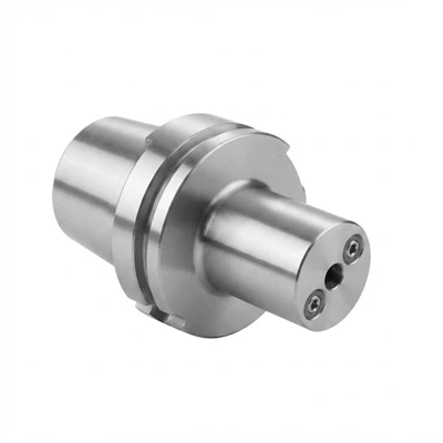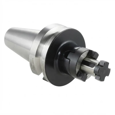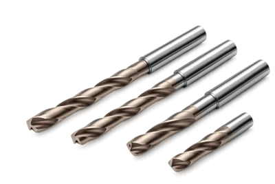

High-Feed Milling Cutters for Automotive Engine Blocks support high-feed rough machining of suitable engine block surfaces, steps and recessed areas. The cutting geometry combines a low lead angle with a shallow axial depth to support high feed per tooth. Tool selection depends on casting material, machining allowance, cutter diameter, spindle capacity and fixture rigidity. Cutter configuration and insert compatibility must match the intended operation.
Key Advantages
High Feed per Tooth
High-feed geometry supports increased feed rates at shallow axial depths. Actual material removal rates depend on cutting speed, radial engagement and machine capacity.
Controlled Cutting Forces
The low lead angle directs a greater proportion of the cutting force axially. Appropriate tool selection and rigid workholding support stable machining.
Replaceable Cutting Edges
Indexable configurations allow worn inserts to be replaced while retaining the cutter body. Usable cutting-edge count depends on the specified insert.
Application-Based Configuration
Cutter dimensions, insert geometry and mounting interfaces can be matched to the machining area and production process.
Applications
Engine Block Roughing
Remove casting stock from suitable external surfaces before finishing operations. Cutter access and engagement must suit the component geometry.
Step and Pocket Milling
Machine accessible steps and recessed areas where the cutter diameter, toolpath and cutting depth meet the application requirements.
Cast Iron Components
Potential applications include gray cast iron and compacted graphite iron. Insert grade selection depends on material properties, casting condition and cutting parameters.
Production Machining
High-feed milling can support stock removal in repeat production operations. Cycle-time improvements should be established through comparable machining trials.
Technical Specifications
|
Parameter |
Specification Example |
|
Product type |
High-feed milling cutter (Indexable) |
|
Cutting method |
High-feed roughing & semi-finishing |
|
Cutter diameter (D) |
50 mm – 160 mm |
|
Number of insert pockets (Z) |
4 – 10 teeth |
|
Maximum axial depth of cut (ap) |
0.8 mm – 2.0 mm |
|
Cutter mounting interface |
Arbor / Shell mill mount (Metric / Inch) |
|
Workpiece material |
Gray Cast Iron (GG25/HT250), CGI |
|
Cutting speed (vc) |
180 m/min – 350 m/min |
|
Feed per tooth (fz) |
0.6 mm/tooth – 1.8 mm/tooth |
|
Radial width of cut (ae) |
50% to 80% of cutter diameter |
Cutter Configuration
Cutter Body
The body determines the cutting diameter, insert-pocket layout, mounting interface and overall dimensions. These features must match the machine setup and machining clearance.
Insert Geometry
Insert shape, edge preparation and carbide grade determine material compatibility and cutting behavior. Confirm the complete insert designation before ordering replacements.
Clamping Components
Insert seats and fastening components maintain insert positioning. Assembly must follow the specified clamping procedure and tightening torque.
Workpiece Material Compatibility
Gray Cast Iron
Select the carbide grade according to hardness, casting skin, inclusions and machining allowance.
Compacted Graphite Iron
Evaluate the insert grade against material strength, cutting resistance and expected edge loading. Confirm cutting conditions through application data.
Interrupted Cutting
Casting surfaces and variable stock allowances can change cutting loads. The toolpath and insert geometry should reflect the actual machining sequence.
Tool Selection Guide
Stock Allowance
Determine the material to be removed and the finishing allowance. Keep axial depth and radial engagement within the selected tool's specified limits.
Machine Capacity
Check spindle power, torque, tool overhang and fixture rigidity before setting feed rates.
Surface Requirements
Define the required flatness, surface finish and remaining finishing allowance to establish the roughing strategy.
Cutting Parameters
Select cutting speed, feed per tooth, axial depth and radial width according to the cutter geometry, insert grade and workpiece material.
Customization Options
Drawing-Based Design
Provide component drawings and machining-area dimensions to assess the required cutter geometry and access.
Dimensional Configuration
Review cutter diameter, overall length, mounting interface and insert arrangement against the machining setup.
Application Matching
Workpiece material, stock allowance, production volume and finishing requirements guide tool selection.
Technical Review
Confirm dimensional feasibility, insert compatibility and cutting requirements before approving the configuration for production.
Quality Control
Dimensional Inspection
Check critical dimensions, mounting interfaces and insert-pocket geometry against approved drawings.
Assembly Verification
Inspect insert seating, fastening components and assembly dimensions according to the applicable inspection procedure.
Material Traceability
Maintain material and grade identification through applicable production records. Inspection documentation should correspond to the confirmed tool configuration.
Ordering Information
Application Details
Provide the engine block material, casting condition, machining allowance and operation type.
Tool Dimensions
Specify the required cutter diameter, mounting interface, overall length and insert configuration.
Technical Documents
Component drawings, existing tool designations and machining-area dimensions help establish the required specification.
Order Confirmation
Confirm the model, compatible inserts, supplied components, quantity and delivery requirements before placing an order.
Frequently Asked Questions
Q: Are high-feed cutters suitable for engine block machining?
A: They can support compatible roughing operations when the cutter geometry, workpiece material and machine conditions are properly matched.
Q: Which materials can be machined?
A: Potential applications include gray cast iron and compacted graphite iron, subject to insert-grade recommendations and cutting conditions.
Q: How are cutting parameters selected?
A: Cutting speed, feed per tooth, axial depth and radial engagement depend on the selected tool, insert grade, workpiece and machine setup.
Q: Can cutter dimensions be customized?
A: Custom configurations can be evaluated using component drawings, mounting dimensions and machining requirements.
Q: What information is needed for a quotation?
A: Provide cutter dimensions, mounting interface, workpiece material, application details and order quantity.
Q: Can replacement inserts be ordered separately?
A: Compatible inserts can be specified by the exact insert designation, carbide grade and cutter model.
Hot Tags: high-feed milling cutters for automotive engine blocks, China high-feed milling cutters for automotive engine blocks manufacturers, suppliers, factory, end mill for 60 HRC steel, End Mills for High Hardness Steel, indexable shoulder mill, micro end mill, Replaceable Head Drill, thread milling cutters