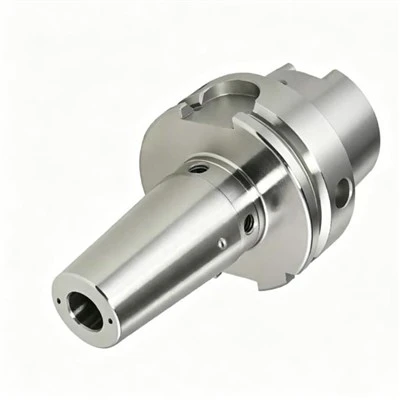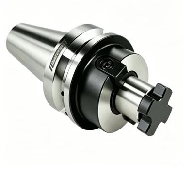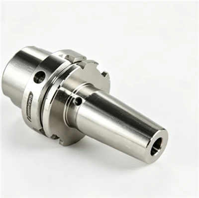

BT Hydraulic Tool Holders clamp compatible cylindrical-shank cutting tools through an internal hydraulic expansion mechanism. The system provides concentric clamping and helps control radial runout and vibration in precision CNC machining. BT30, BT40 and BT50 configurations can be specified according to spindle interface, tool diameter, gauge length and coolant requirements. Selection should match the tool shank, machining operation and required operating speed.
Key Features
Hydraulic Clamping
Internal pressure expands the clamping sleeve around the tool shank, supporting uniform contact when the shank diameter and tolerance meet the specified requirements.
Runout Control
Concentric clamping helps limit radial runout, supporting consistent hole quality and surface finish in suitable drilling, reaming and finishing operations.
Vibration Damping
The hydraulic mechanism helps absorb machining vibration. Tool projection, cutting parameters and spindle condition remain important factors in process stability.
Tool Change Convenience
A clamping screw activates the hydraulic mechanism without a separate heating unit. Follow the specified tightening procedure and minimum insertion depth for the selected model.
Technical Specifications
|
Parameter |
Specification |
|
Product type |
BT Hydraulic Tool Holder |
|
Spindle interface |
BT30 / BT40 / BT50 |
|
Spindle taper ratio |
7:24 |
|
Tool shank type |
Cylindrical (h6 recommended) |
|
Clamping diameters |
6, 8, 10, 12, 16 mm |
|
Gauge lengths |
75 mm, 90 mm |
|
Clamping mechanism |
Hydraulic expansion |
|
Runout tolerance |
≤0.003 mm |
|
Max. operating speed |
Up to 20,000 – 25,000 RPM |
|
Balance grade |
G2.5 |
|
Coolant arrangement |
AD/B type through-tool coolant |
|
Custom dimensions |
Subject to drawing review |
How to Select the Right Holder
Spindle Interface
Match BT30, BT40 or BT50 to the machine spindle. Confirm taper dimensions, flange geometry and retention knob thread before installation.
Tool Shank Diameter
Select the holder bore to match the actual shank diameter and tolerance. Confirm the required insertion depth and usable clamping length.
Gauge Length
Choose sufficient reach for the workpiece feature while keeping tool projection as short as practical. Longer projection can increase deflection and vibration.
Speed and Runout
Specify the required spindle speed and runout tolerance. Verify the rated speed and balance grade for the complete holder assembly, including the cutting tool where applicable.
Applications
Precision Drilling and Reaming
Suitable for selected operations where tool alignment and radial runout affect hole accuracy and surface finish.
Finish Milling
Applicable to finishing cuts that require controlled tool positioning and stable cutting conditions.
Mold and Die Machining
Extended-reach or reduced-profile configurations can be evaluated for deep cavities, recessed surfaces and restricted access.
Precision Components
Suitable for selected machining processes requiring repeatable tool clamping and consistent dimensional results.
Application suitability depends on cutting forces, tool geometry, workpiece material, tool projection and operating conditions.
Compatibility and Configuration
Tool Requirements
Confirm shank diameter, tolerance, contact length and insertion depth. Use compatible cylindrical-shank tools within the specified clamping range.
Coolant Delivery
Specify through-tool coolant or external delivery as required. Confirm internal passage design, sealing requirements and permitted coolant pressure for the selected model.
Machine Clearance
Check holder body dimensions, tool-changing clearance, retention knob compatibility and total assembly length before use.
Custom Hydraulic Tool Holders
Custom configurations can be reviewed against technical drawings and machining requirements.
Interface and Dimensions
Specify the BT interface, clamping diameter, gauge length, overall length and required body profile.
Reach and Clearance
Slim or extended configurations can be assessed for restricted machining areas, subject to rigidity and clearance requirements.
Coolant Configuration
Provide the required coolant route, operating pressure and sealing details where applicable.
Submit a dimensioned drawing, tool specifications and operating conditions for technical review before confirming the final design.
Quality Control and Inspection
Dimensional Inspection
Check spindle-interface dimensions, clamping bore and overall length against the approved drawing.
Runout Measurement
Measure total indicated runout using the specified test arbor, measurement position and inspection method. Compare the result with the agreed tolerance.
Balance Verification
Confirm the specified balance grade and maximum operating speed for the applicable configuration.
Inspection Documentation
Dimensional reports and agreed inspection records can be specified with the order, subject to the available inspection process.
Ordering Information
Provide the following information for configuration review and quotation:
- BT interface and retention knob requirements.
- Tool shank diameter and tolerance.
- Required gauge length and overall length.
- Runout tolerance, spindle speed and balance requirements.
- Coolant arrangement and operating pressure, where applicable.
- Quantity, technical drawing and inspection documentation requirements.
Complete specifications help establish the required configuration before quotation and production confirmation.
Frequently Asked Questions
Q: Which BT interfaces can be specified?
A: BT30, BT40 and BT50 are the principal interface options. Confirm model availability and the required spindle-side dimensions.
Q: Which tool diameters are available?
A: Reference sizes include 6, 8, 10, 12 and 16 mm. Confirm the available bore sizes and permitted shank tolerances for the selected configuration.
Q: Can hydraulic tool holders be used at high spindle speeds?
A: Confirm the model's rated speed, balance grade, tool assembly and machine operating requirements before high-speed operation.
Q: Can dimensions and coolant arrangements be customized?
A: Custom dimensions, gauge length, body profile and coolant arrangements can be reviewed against technical drawings and operating requirements.
Q: What information is needed for a quotation?
A: Provide the spindle interface, tool diameter, required length, speed and accuracy requirements, coolant details, quantity and relevant drawings.
Hot Tags: bt hydraulic tool holders, China bt hydraulic tool holders manufacturers, suppliers, factory, custom tool holder, ER Spring Collet Tool Holder NT, Flange ER Collet Tool Holder, High Speed Chuck, lathe tool holder, Precision NT ER Collet Chuck