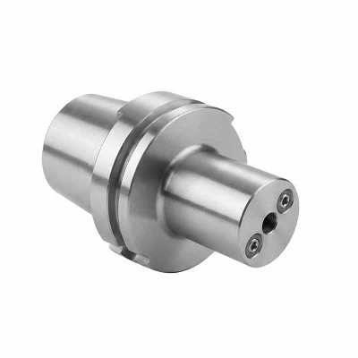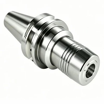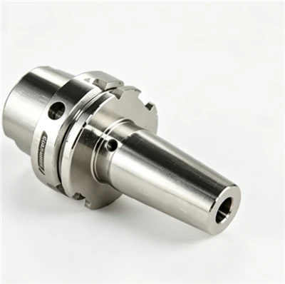

Slim Hydraulic Tool Holders combine hydraulic expansion clamping with a narrow nose profile for precision machining in restricted spaces. The internal clamping mechanism secures cylindrical-shank cutting tools, while the reduced nose diameter provides clearance around fixtures, recessed features and deep cavities. Typical applications include precision drilling, reaming and finishing. Selection depends on spindle interface, tool shank diameter, holder dimensions, projection length and operating conditions.
Key Advantages
Compact Nose Geometry
The narrow profile provides additional clearance around workpiece features and fixtures to avoid interference during complex multi-axis machining paths.
Hydraulic Clamping
Internal hydraulic pressure applies uniform radial force around the tool shank to support consistent tool positioning and clamping stability.
Repeatable Tool Installation
The hydraulic mechanism enables consistent setup and tool changeover when the tool shank, clamping bore and contact surfaces meet specified tolerances.
Finishing Process Control
A properly matched holder supports controlled runout and stable tool performance during precision drilling, reaming and finishing operations.
Technical Specifications
|
Parameter |
Reference Value |
|
Product Type |
Slim Hydraulic Tool Holder |
|
Clamping Mechanism |
Hydraulic Expansion |
|
Clamping Diameter |
6, 8, 10, 12, 16 mm |
|
Projection Length |
80, 100, 120 mm |
|
Nose Diameter |
24, 28, 32 mm |
|
Overall Length |
110, 130, 150 mm |
|
Spindle Interface |
BT, HSK, BBT, CAT |
|
Runout Accuracy |
≤ 0.003 mm |
|
Maximum Speed |
25,000 RPM |
|
Balance Grade |
G2.5 |
|
Tool Shank Tolerance |
h6 |
|
Coolant Configuration |
Through-coolant available |
Applications
Precision Drilling
Suitable for high-speed drilling operations where holder clearance affects access to the machining point and hole depth.
Reaming and Hole Finishing
Hydraulic clamping supports concentric tool positioning for operations requiring controlled hole dimensions and surface finish quality.
Die and Mold Machining
The narrow nose improves access around deep cavities, ribs and recessed features when the holder envelope provides sufficient clearance.
Complex Contour Finishing
Designed for applications where tool approach, projection length and fixture interference require careful setup planning.
How to Select the Right Holder
Spindle Interface
Match the interface type and size to the machine spindle specification, including the required retention arrangement.
Tool Shank Diameter
Confirm the nominal diameter, shank tolerance and usable clamping length against the holder approved specifications.
Nose Clearance
Compare the maximum holder diameter with the workpiece profile, fixture dimensions and required tool approach.
Projection Length
Select the shortest projection that provides sufficient reach while evaluating rigidity for the intended process.
Operating Conditions
Check the approved rotational speed, cutting load, coolant arrangement and runout requirements for the intended process.
Customization Options
Clamping Dimensions
Submit the required clamping diameter, nose dimensions and projection length for technical assessment.
Interface Configuration
Provide the required spindle interface and dimensional drawing to establish compatibility with the intended machine connection.
Coolant Arrangement
Specify the required coolant delivery method and connection details for configuration review.
Drawing-Based Development
Custom configurations can be evaluated against application drawings and manufacturing requirements. Final dimensions and tolerances require engineering confirmation.
Quality Control and Documentation
Dimensional Inspection
Verify critical interface dimensions, clamping bore, nose diameter and overall length against approved technical drawings.
Runout Measurement
Define the measurement position, test mandrel and inspection method to establish consistent acceptance criteria.
Balance Verification
Specify the required balance grade and operating speed for the selected configuration prior to shipment.
Technical Records
Confirm the availability of applicable drawings, inspection reports and configuration records before order approval.
Ordering Information
Required Dimensions
Specify the spindle interface, tool shank diameter, nose diameter and projection length.
Application Details
Provide the cutting tool type, workpiece material, operating speed and available machining clearance.
Order Requirements
State the required quantity, dimensional tolerances, customization requirements and applicable inspection documents.
Frequently Asked Questions
Q: What is a slim hydraulic tool holder used for?
A: It combines hydraulic clamping with a narrow nose profile for precision machining where tool access and clearance are restricted.
Q: Which clamping diameters are available?
A: Standard clamping diameters range from 6 mm to 16 mm, with specific sizes determined by the selected model.
Q: How should runout accuracy be evaluated?
A: Check the specified tolerance, measurement position, test mandrel and inspection conditions defined in the technical data.
Q: Can the holder support through-coolant machining?
A: Compatibility depends on the internal coolant passages and spindle interface configuration. Confirm the details before selection.
Q: Can custom dimensions be requested?
A: Custom dimensions can be submitted for engineering assessment based on application drawings and manufacturing requirements.
Hot Tags: slim hydraulic tool holders, China slim hydraulic tool holders manufacturers, suppliers, factory, cnc end mill holder, CNC Screw in Milling Cutter Holder, ER Spring Collet Tool Holder BT, ER Spring Collet Tool Holder GOST, Indexable Boring Bar Holder, milling spindle tool holder