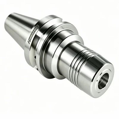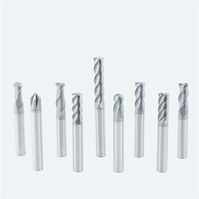
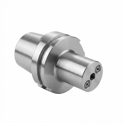
HSK-A Hydraulic Tool Holders secure compatible cylindrical-shank cutting tools through an internal hydraulic expansion mechanism. The clamping system applies radial pressure around the tool shank to support concentric positioning and vibration control. The HSK-A interface connects the holder to a matching spindle. Typical applications include precision drilling, reaming and finishing operations where tool runout, surface finish and setup consistency matter. Selection depends on interface size, shank diameter, gauge length, spindle speed and the required machining tolerance.
Key Advantages
Radial Clamping
Hydraulic pressure acts around the compatible tool shank, supporting uniform contact and accurate tool positioning.
Vibration Damping
The hydraulic chamber helps absorb cutting vibration in suitable machining conditions, supporting stable finishing and consistent surface quality.
Repeatable Positioning
A defined clamping procedure helps maintain consistent tool setup between machining runs.
Simplified Tool Changes
The hydraulic mechanism clamps the tool through a dedicated actuation system. Follow the specified operating procedure for the selected holder.
Technical Specifications
|
Parameter |
Specification |
|
Product Type |
Hydraulic Expansion Tool Holder |
|
Spindle Interface |
HSK-A |
|
Interface Size |
HSK-A63 / HSK-A100 |
|
Clamping Diameter |
20 mm |
|
Clamping Diameter Range |
6–32 mm |
|
Gauge Length |
105 mm |
|
Clamping Mechanism |
Hydraulic Expansion |
|
Shank Tolerance |
h6 |
|
Runout Accuracy |
≤ 0.003 mm |
|
Balance Grade |
G2.5 at 25,000 RPM |
|
Maximum Spindle Speed |
25,000 RPM |
|
Coolant Configuration |
Through-Tool Coolant (AD/B Style) |
|
Custom Dimensions |
Available Upon Drawing Review |
Application
Precision Drilling
Suitable configurations support drilling operations requiring accurate tool positioning and consistent hole quality.
Reaming
Hydraulic clamping can support concentric tool positioning for finishing holes to specified dimensional and surface requirements.
Finishing Milling
Compatible tools can be used for finishing operations when cutting loads, projection and spindle speed remain within the holder's rated limits.
Mold and Die Machining
Selected configurations suit cavity and contour finishing where tool stability and repeatable setups are important.
Product Selection Guide
Spindle Interface
Match the HSK-A size to the spindle specification. Confirm the interface dimensions and contact surfaces against the approved drawing.
Tool Shank Diameter
Select the clamping bore for the actual shank diameter and specified tolerance. Check the required insertion length before installation.
Gauge Length
Choose the projection required for workpiece access. Review fixture clearance and avoid unnecessary tool overhang.
Operating Requirements
Confirm the required runout, balance grade, rotational speed and cutting load against the selected model's specifications.
Configuration Options
Overall Dimensions
Gauge length, nose diameter and body geometry can be reviewed against workpiece access and fixture clearance requirements.
Coolant Supply
Specify through-tool coolant or the required alternative. Confirm passage compatibility and the permitted operating pressure.
Axial Adjustment
State the required tool-length adjustment range and confirm compatibility with the selected holder design.
Customization Service
Custom configurations can be assessed against dimensional drawings and machining requirements. Options for review include gauge length, nose diameter, clamping bore and coolant arrangement. Provide the interface size, tool shank dimensions, required projection and operating speed. The drawing review establishes the dimensional requirements and confirms the feasible configuration.
Quality Control & Technical Verification
Dimensional Inspection
Verify the spindle interface, clamping bore and overall dimensions against the approved drawing.
Runout Measurement
Define the test mandrel, measurement position and permitted deviation. Record the result against the specified acceptance criteria.
Balance Verification
Identify the required balance grade and corresponding rotational speed for the selected configuration.
Technical Documentation
Specify the required dimensional report, inspection records and approved drawing revision for order verification.
Ordering Information
Provide the following information for model selection:
HSK-A interface size
1
>>
Tool shank diameter and tolerance
2
>>
Required gauge length and overall length
3
>>
Runout and balance requirements
4
>>
Maximum spindle speed
5
>>
Coolant arrangement
6
>>
Quantity and dimensional drawing, where applicable
7
Frequently Asked Questions
Q: How does a hydraulic tool holder clamp a cutting tool?
A: An internal hydraulic mechanism applies radial pressure around a compatible cylindrical tool shank.
Q: How do I select the correct HSK-A interface?
A: Match the interface size and dimensions to the spindle specification.
Q: Which tool shanks are compatible?
A: Compatibility depends on shank diameter, tolerance, insertion length and the holder's specified clamping range.
Q: Can special dimensions be requested?
A: Custom dimensions can be reviewed against technical drawings and application requirements.
Q: How is runout specified?
A: State the required deviation, test mandrel and measurement position so the acceptance criteria are clearly defined.
Hot Tags: hsk-a hydraulic tool holders, China hsk-a hydraulic tool holders manufacturers, suppliers, factory, ER Spring Collet Tool Holder SK, ER Tool Holder, HSK T Indexable Boring Bar Holder, Screw in Milling Tool Holder, SKS Precision Collet, threading tool holder