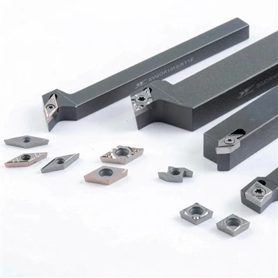

The series is built from double-sided, CVD-coated carbide inserts engineered for ISO P steel, from light finishing through severe interrupted heavy cutting. It pairs eight application-matched chipbreaker geometries - PF, PL, PM, PE, PR, PX, PY and PH - with three newly developed grades, GPT6220, GPT6225 and GPT6230, across the full ISO shape portfolio: CNMG, DNMG, SNMG, TNMG, WNMG, VNMG, KNUX and RNMG.
Because every insert is negative (0° clearance), both faces cut: a CNMG gives you four usable edges, a WNMG six, an SNMG eight - twice as many as a single-sided positive insert of the same corner size. On stable CNC lathes working carbon steel, alloy steel and cast steel, that is where the cost advantage comes from.
Specification
|
Attribute |
Specification |
|
ISO application class |
P - steel (carbon, alloy, cast steel, ferritic / martensitic stainless) |
|
Insert style |
Negative, 0° clearance, double-sided |
|
Shapes available |
CNMG, DNMG, SNMG, TNMG, WNMG, VNMG, KNUX, RNMG |
|
Chipbreaker geometries |
PF, PL, PM, PE, PR, PX, PY, PH (8 total) |
|
Matched grades |
GPT6220 · GPT6225 · GPT6230 |
|
Coating |
Multilayer CVD - TiN / TiCN / Al₂O₃ |
|
Cutting edges per insert |
4 (C, D, V) · 6 (T, W) · 8 (S) |
|
Corner radii |
0.4 · 0.8 · 1.2 · 1.6 · 2.0 mm and inch equivalents |
|
Depth of cut range |
0.3 mm (PF finishing) to 8 mm (PH heavy cutting) |
|
Compatibility |
ISO 1832 - fits any conforming negative holder |
What "Negative P Series" Means
P is the ISO 513 material class for steel. A P-class insert is engineered for the long, ductile chips and the crater-wear pattern that carbon steel, alloy steel and cast steel produce. Running a P insert in stainless or cast iron is one of the most common causes of unpredictable tool life on a shop floor.
Negative is the 0° clearance angle, and it is the real performance lever. A 90° edge angle is blunt and thick, so it survives an interrupted cut or a forged, scaled surface far better than a sharp positive edge. And because no clearance is ground into the top face, the insert is symmetrical and can be flipped - that is where the doubled edge count comes from.
The trade-off is cutting force: a negative edge needs a rigid setup, with solid workholding, short overhangs and enough spindle power and mass to absorb the load. On a light machine or a thin-walled part, use a positive geometry instead.
Eight Chipbreaker Geometries: PF, PL, PM, PE, PR, PX, PY, PH
The chipbreaker decides whether a chip curls and breaks or wraps around the chuck as a bird's nest. Each geometry is matched to a narrow band of depth of cut and feed.
|
Geometry |
Operation |
Depth of cut (ap) |
Feed (fn) |
Design feature |
|
PF |
Finishing |
0.3–1.5 mm |
0.08–0.25 mm/rev |
Three-stage intelligent chip-breaking platform |
|
PL |
Finishing to semi-finishing |
0.5–2.0 mm |
0.15–0.30 mm/rev |
Wave-shaped cutting edge |
|
PM |
Semi-finishing |
1.0–3.0 mm |
0.20–0.40 mm/rev |
Positive rake, double-antenna raised land |
|
PE |
Semi-finishing |
1.0–3.0 mm |
0.20–0.40 mm/rev |
High edge strength geometry |
|
PR |
Roughing |
2.0–5.0 mm |
0.30–0.55 mm/rev |
Flat, large edge-width land |
|
PX |
Heavy cutting |
3.0–8.0 mm |
0.40–0.80 mm/rev |
Inclination angle, reduced cutting resistance |
|
PY |
Heavy cutting |
3.0–8.0 mm |
0.40–0.80 mm/rev |
Flat, large edge-width land with strong chip breaking |
|
PH |
Heavy cutting |
3.0–8.0 mm |
0.40–0.80 mm/rev |
Wavy-line protrusion, balanced resistance vs. chip control |
Read the three groups:
PF and PL finish. PF is the first choice, with a three-stage platform that reaches depths and feeds conventional geometries cannot. PL adds a wave-shaped edge for profiling where the depth of cut fluctuates.
PM and PE cover semi-finishing. PM is the general-purpose option - positive rake to bring resistance down, a double-antenna land to break the chip. PE trades chip-breaking for edge strength when the setup, not the chip, is the problem.
PR, PX, PY and PH remove the bulk of the material. PR roughs with a flat, large edge-width land that survives the first scale-removing passes. PX reduces resistance through an inclination angle where machine power limits your depth of cut. PY holds edge strength on continuous heavy passes. PH, the first choice for heavy cutting, balances resistance against chip control with a wavy-line protrusion.
Matched Grades: GPT6220, GPT6225, GPT6230
|
Grade |
Substrate character |
Recommended operation |
Cutting conditions |
|
GPT6220 |
High-hardness cemented carbide |
Finishing to semi-finishing |
Continuous and light interrupted |
|
GPT6225 |
Tough-reinforced carbide, balanced |
Semi-finishing |
General continuous and interrupted |
|
GPT6230 |
Tough-reinforced carbide, maximum toughness with comparable wear resistance |
Semi-finishing to roughing |
Most interrupted conditions |
All three grades carry a newly developed multilayer CVD coating with exceptional adhesion, on substrates produced under the GEFORTECH process: the coating supplies wear resistance, the substrate supplies toughness.
GPT6220 is the wear-resistance grade - the highest cutting-speed capability of the three, and the longest tool life of the three on clean continuous cuts. GPT6225 is the balanced workhorse that covers most shop-floor work. GPT6230 is the toughness grade, for interrupted cuts, unbalanced parts and forged skins. Moving down the list trades speed for survival.
All three are also available across the Negative Q, Negative G and Positive U series, so one grade can be standardised across a mixed tool inventory.
Insert Shapes and ISO Size Codes
Every P series insert follows ISO 1832, so the code on the box tells you exactly what you are holding. In CNMG120408: C 80° rhombic · N negative, 0° clearance · M tolerance class · G double-sided, centre hole, ground periphery · 12 12 mm inscribed circle · 04 4.76 mm thickness · 08 0.8 mm corner radius.
|
Shape |
Included angle |
Cutting edges |
ISO example |
ANSI equivalent |
Typical use |
|
C - CNMG |
80° rhombic |
4 |
CNMG120408 |
CNMG432 |
General turning, facing, profiling - the default negative shape |
|
D - DNMG |
55° rhombic |
4 |
DNMG150608 |
DNMG442 |
Profiling and copy turning, good accessibility |
|
S - SNMG |
90° square |
8 |
SNMG120408 |
SNMG432 |
Heavy roughing and facing, maximum edges per insert |
|
T - TNMG |
60° triangle |
6 |
TNMG160408 |
TNMG332 |
General turning where a triangle is already tooled |
|
W - WNMG |
80° trigon |
6 |
WNMG080408 |
WNMG431 |
Roughing to semi-finishing, strong edge with good economy |
|
V - VNMG |
35° rhombic |
4 |
VNMG160404 |
VNMG331 |
Fine profiling, tight radius features |
|
K - KNUX |
55° parallelogram |
2 |
- |
- |
Copy turning, light finishing |
|
R - RNMG |
Round |
Multiple |
RNMG120400 |
RNMG42 |
Hard materials, heavy stock removal, interrupted surfaces |
The last two digits of the ANSI code give the nose radius in 64ths of an inch: CNMG432 is a 2/64 inch radius, or 0.8 mm. Order by whichever code your shop uses.
Recommended Starting Cutting Parameters
|
Geometry |
Operation |
Vc (m/min) |
fn (mm/rev) |
ap (mm) |
|
PF |
Finishing |
180–300 |
0.08–0.25 |
0.3–1.5 |
|
PL |
Finishing to semi-finishing |
160–280 |
0.15–0.30 |
0.5–2.0 |
|
PM |
Semi-finishing |
150–260 |
0.20–0.40 |
1.0–3.0 |
|
PE |
Semi-finishing, unstable |
130–230 |
0.20–0.40 |
1.0–3.0 |
|
PR |
Roughing |
120–220 |
0.30–0.55 |
2.0–5.0 |
|
PX / PY / PH |
Heavy cutting |
100–180 |
0.40–0.80 |
3.0–8.0 |
Starting values for CVD-coated negative inserts in ISO P steel. For interrupted cuts, reduce Vc by 15–25% and move one step down in geometry. Confirm the final window against SW technical team.
Application Case: Half Shaft Roughing in 40Cr
In a documented production run, a WNMG080408-PM insert in grade GPT6220 roughed a 40Cr (AISI 5140 equivalent) half shaft at HB 200–340 - 75–219 m/min, 0.29 mm/rev, 1–2 mm depth of cut, dry. The PM geometry held chip control across the full depth-of-cut band while the GPT6220 CVD coating carried the surface speed on hardened alloy steel: a stable, predictable roughing operation on a part that is difficult to hold.
Negative vs. Positive Inserts
|
Negative (this series) |
Positive |
|
|
Clearance angle |
0° |
5–11° |
|
Edge strength |
High - blunt 90° edge |
Lower - sharp edge chips more easily |
|
Cutting force |
High - needs a rigid machine |
Low - suits light machines and long overhangs |
|
Edges per insert |
4–8, double-sided |
2, single-sided |
|
Cost per edge |
Lowest |
Higher |
|
First choice for |
Roughing, interrupted cuts, hard steel, high-volume production |
Finishing, boring, thin walls, non-ferrous |
Choose the Negative P Series when the part is held rigidly, the machine has the power and mass, the cut is heavy or interrupted, or tool cost per edge drives the decision - the standard configuration for shafts, gears, hubs and flanges. Choose a positive geometry when the part is thin-walled, the boring bar overhangs far, the lathe is small or worn, or you are finishing and need the lowest cutting force.
How to Select the Right Insert
Start from the holder you already own. The holder code fixes shape, clearance, hand and clamping style.
Fix the size and corner radius against the holder spec and the part feature: small radii for finishing and weak parts, large radii for roughing strength.
Pick the chipbreaker from the cut you will really run, using its actual depth of cut and feed.
Pick the grade from cut stability: clean and continuous, GPT6220; mixed, GPT6225; interrupted or unbalanced, GPT6230.
Start in the middle of the Vc window and watch the chip. Short, curled, silver-to-brown chips mean you are right; stringy chips mean the feed is too low for the geometry, blue chips mean the speed is too high.
Hot Tags: negative turning inserts, China negative turning inserts manufacturers, suppliers, factory, acme carbide threading inserts, api threading inserts, carbide inserts for buttress threads, carbide threading inserts, Indexable Milling Insert, Thread Turning Insert