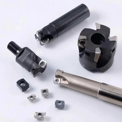
GL Grade ODKT Milling Inserts are indexable carbide inserts for light face milling and controlled material removal. The positive cutting geometry supports reduced cutting resistance under suitable machining conditions. Selection depends on insert dimensions, carbide grade, workpiece material and cutter compatibility. Matching these factors helps establish a suitable configuration for finishing operations and repeat production.
Key Advantages
Reduced Cutting Resistance
The positive rake geometry supports smooth cutting engagement during light milling. Actual cutting forces depend on workpiece material, feed per tooth, depth of cut and tool setup.
Indexable Design
The octagonal insert format provides multiple cutting edges, subject to the specified geometry and compatible cutter. Correct indexing and seating help maintain consistent cutting positions.
Finishing Control
The GL geometry supports light material removal where cutting stability and surface quality matter. Results depend on runout, edge condition, feed rate and machine rigidity.
Grade Flexibility
Carbide grades and coatings can be evaluated according to workpiece material, hardness and cutting conditions. Confirm the exact grade before application.
Technical Specifications
|
Parameter |
Specification (Reference) |
|
Product Type |
Indexable Face Milling Insert |
|
Insert Shape |
Octagonal (ODKT) |
|
Geometry |
GL (Light Cutting) |
|
Reference Model |
ODKT060508-GL |
|
Insert Length (L) |
6.50 mm |
|
Inscribed Circle (IC) |
15.875 mm |
|
Insert Thickness (S) |
5.56 mm |
|
Fixing Hole (D1) |
5.56 mm |
|
Corner Radius (RE) |
0.80 mm |
|
Substrate |
Cemented Carbide |
|
Coating |
PVD TiAlN / AlCrN |
|
Workpiece Material |
ISO P, M, K (Steel, Stainless Steel, Cast Iron) |
|
Cutting Speed (vc) |
120–250 m/min (Steel) / 80–180 m/min (Stainless Steel) |
|
Feed per Tooth (fz) |
0.08–0.22 mm/tooth |
|
Maximum Depth of Cut (ap) |
0.5–2.0 mm |
Applications
Light Face Milling
Suitable for evaluating flat-surface milling where the insert geometry matches the cutter pocket and the required cutting load.
Finishing Passes
Applicable to light finishing cuts where controlled material removal and consistent tool positioning are required.
Steel and Cast Iron
Select a carbide grade approved for the specific material and hardness. Confirm the recommended application range before production use.
Aluminium Alloys
Verify that the selected grade and cutting geometry suit the alloy. Consider chip formation, edge condition and surface-finish requirements during setup.
Insert Selection Guide
Workpiece Material
Identify the material designation and hardness. Match the carbide substrate and coating to the intended application rather than selecting by insert shape alone.
Cutting Load
Confirm cutting speed, feed per tooth and depth of cut against the recommended range for the selected grade and cutter.
Dimensional Fit
Compare IC, thickness, fixing hole and corner radius with the existing insert drawing. Confirm the complete designation before replacement.
Surface Finish
Specify the required finish and dimensional tolerance. Evaluate cutter runout, edge condition and feed per tooth as part of the machining setup.
Tool Compatibility and Machining Setup
Cutter Pocket
Verify the exact insert designation and seating geometry against the cutter specification.
Clamping
Check the fixing hole, screw and contact surfaces. Clean the insert pocket before installation to support correct seating.
Runout Control
Inspect cutter condition and insert positioning when surface consistency is important. Uneven seating can affect cutting load and finish.
Cutting Parameters
Use grade-specific recommendations for the workpiece material. Validate speed, feed and depth of cut under actual machining conditions.
Customization Options
Dimensions
Submit the required drawing, dimensions and tolerances for technical review.
Cutting Geometry
Specify the required GL configuration and machining application. Geometry changes require feasibility confirmation.
Carbide Grade and Coating
Provide the workpiece material, hardness and cutting conditions to support grade selection.
Packaging and Identification
Confirm package quantity, labeling and product identification requirements before order approval.
Quality and Consistency
Dimensional Inspection
Check IC, thickness, fixing hole and corner radius against the approved drawing and specified tolerances.
Edge Condition
Define edge preparation and acceptance criteria according to the intended machining operation.
Product Identification
Record the insert designation, carbide grade and coating against the approved specification.
Repeat-Order Control
Retain the approved drawing revision and configuration details to support consistent replenishment.
Ordering Information
Prepare the following details for quotation and technical review:
Insert model and required quantity.
Dimensional drawing or existing part reference.
Workpiece material and hardness.
Cutter designation or pocket dimensions.
Required carbide grade and coating.
Packaging, labeling and delivery requirements.
Frequently Asked Questions
Q: What does GL mean?
A: GL identifies the light-cutting geometry. The carbide grade is a separate designation that determines the recommended material range.
Q: Which materials can these inserts machine?
A: Suitability depends on the selected carbide grade, coating and machining conditions. Confirm the grade-specific recommendations for the intended material.
Q: How can compatibility with an existing cutter be confirmed?
A: Compare the insert designation, IC, thickness, fixing hole, corner radius and seating geometry with the cutter specification.
Q: Can customized dimensions be requested?
A: Customized dimensions can be reviewed against the drawing, tolerance requirements and confirmed manufacturing capabilities.
Q: How should cutting parameters be selected?
A: Use verified recommendations for the selected grade and workpiece material. Adjust speed, feed and depth of cut according to cutter specifications and machining results.
Hot Tags: gl grade odkt milling inserts for light cutting, China gl grade odkt milling inserts for light cutting manufacturers, suppliers, factory, carbide end mill for aluminum, Drilling and Boring Tools, End Mills for 304 Stainless Steel, indexable shoulder mill, Micro Carbide End Mills, Replaceable Head Drill