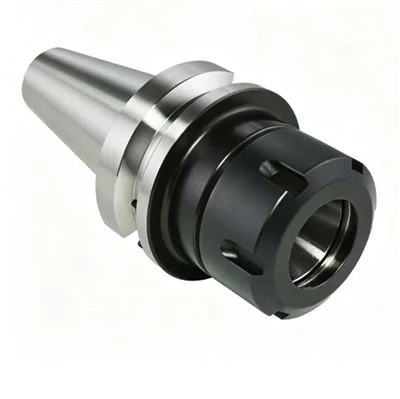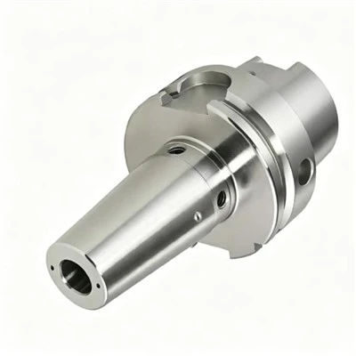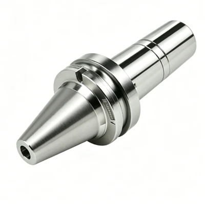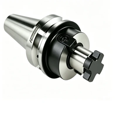
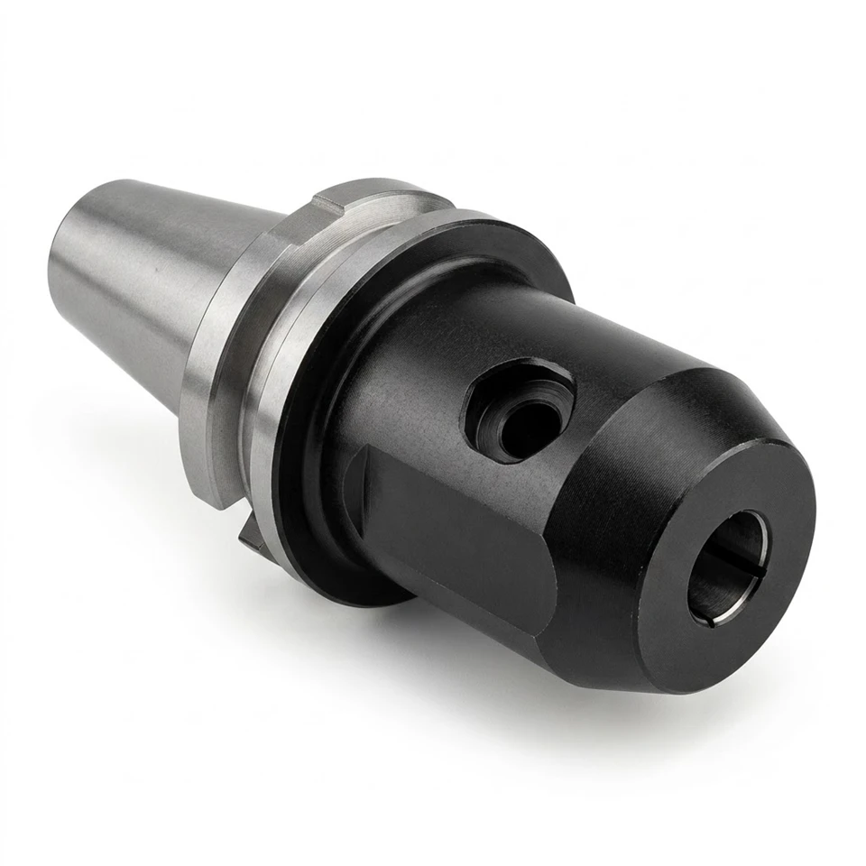
This End Mill Holder is a classic mechanical clamping device featuring a two-part structure: a standard tapered shank at the rear (inserted into the machine spindle to ensure concentricity and rigidity) and a reinforced black side-lock clamping head at the front. The clamping head is equipped with a dedicated set screw on its side.
Its operating principle is straightforward and reliable: once the milling cutter shank-which features a flat section-is inserted into the bore, tightening the side screw presses its tip firmly against that flat surface. This "surface-to-surface" rigid locking mechanism provides exceptional resistance to torsional forces.
Product Features
1. Taper Shank
High-Precision Grinding: The silvery-white tapered section shown in the image is the critical interface connecting to the machine tool spindle. This section typically undergoes carburizing, hardening, and precision grinding, resulting in an exceptionally smooth surface finish.
Standard Interface: The taper must strictly adhere to international standards (such as BT, SK, CAT, or HSK interfaces) to ensure perfect coaxiality upon insertion and extensive surface contact, thereby effectively transmitting the spindle's torque.
2. Flange & V-Groove
V-Groove (Tool Change Groove): A grooved ring sits between the silver taper shank and the black body. This feature is specifically designed for the CNC machine's Automatic Tool Changer (ATC) system; the robotic arm engages this groove to grip and exchange the tool.
Drive Key Slots: Two notches (key slots) are typically located on opposite sides of the flange. These interlock with protruding keys on the spindle face, serving as the primary contact points for transmitting the spindle motor's immense torque.
3. Front Holder Body
Thick-Walled Design: The black cylindrical section shown is significantly more robust than standard spring collet holders (ER holders). This thick-walled design provides superior radial rigidity, enabling the holder to withstand the intense vibrations and bending stresses generated during heavy-duty cutting operations.
Blackened Anti-Rust Finish: The black appearance results from a blackening (oxidation) or coating process. This treatment not only prevents rust and corrosion but also enhances surface hardness and wear resistance to some extent.
4. Set Screw
Locking Mechanism: This is the core feature of the side-lock tool holder. A high-strength hex-socket set screw is housed within the threaded hole on the side of the black body.
Flat or Carbide Tip: The screw typically features a flat tip; when tightened, it presses firmly against the flat section (Weldon Flat) on the milling cutter's shank, creating a secure, rigid mechanical lock.
5. Unseen Internal Details (Inner Bore & Precision)
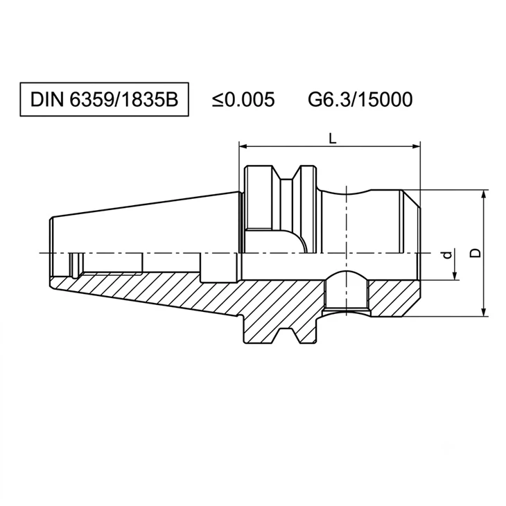
Inner Bore Runout Precision: The tool-mounting bore at the front of the holder must be machined using a high-precision internal cylindrical grinder. For high-quality side-lock tool holders, the concentricity (runout error) between the inner bore and the tapered shank is typically controlled to within 0.005 mm (5 microns).
Dynamic Balance: Because material is removed from the side (for the set screw hole), modern high-quality side-lock tool holders undergo dynamic balancing before leaving the factory-typically meeting G2.5 or G6.3 standards-to prevent centrifugal vibration at high speeds that could damage the machine spindle.
Technical Parameters
|
Size |
d |
D |
L |
M |
Screw Quantity |
|
BT30-SLA06-50 |
6 |
25 |
50 |
M6 |
1 |
|
BT30-SLA08-50 |
8 |
28 |
50 |
M8 |
1 |
|
BT30-SLA10-50 |
10 |
35 |
50 |
M10 |
1 |
|
BT30-SLA12-50 |
12 |
42 |
50 |
M12 |
1 |
|
BT30-SLA14-50 |
14 |
44 |
50 |
M12 |
1 |
|
BT30-SLA16-63 |
16 |
48 |
63 |
M14 |
1 |
|
BT30-SLA18-63 |
18 |
50 |
63 |
M14 |
1 |
|
BT30-SLA20-63 |
20 |
52 |
63 |
M16 |
1 |
|
BT30-SLA25-90 |
25 |
65 |
90 |
M18*2 |
2 |
|
BT40-SLA06-50 |
6 |
25 |
50 |
M6 |
1 |
|
BT40-SLA08-50 |
8 |
28 |
50 |
M8 |
1 |
|
BT40-SLA10-63 |
10 |
35 |
63 |
M10 |
1 |
|
BT40-SLA12-63 |
12 |
42 |
63 |
M12 |
1 |
|
BT40-SLA14-63 |
14 |
44 |
63 |
M12 |
1 |
|
BT40-SLA16-63 |
16 |
48 |
63 |
M14 |
1 |
|
BT40-SLA18-63 |
18 |
50 |
63 |
M14 |
1 |
|
BT40-SLA20-63 |
20 |
52 |
63 |
M16 |
1 |
|
BT40-SLA25-90 |
25 |
65 |
90 |
M18*2 |
2 |
|
BT40-SLA32-100 |
32 |
72 |
100 |
M20*2 |
2 |
|
BT40-SLA40-120 |
40 |
80 |
120 |
M20*2 |
2 |
|
BT40-SLA06-100 |
6 |
25 |
100 |
M6 |
1 |
|
BT40-SLA08-100 |
8 |
28 |
100 |
M8 |
1 |
|
BT40-SLA10-100 |
10 |
35 |
100 |
M10 |
1 |
|
BT40-SLA12-100 |
12 |
42 |
100 |
M12 |
1 |
|
BT40-SLA14-100 |
14 |
44 |
100 |
M12 |
1 |
|
BT40-SLA16-100 |
16 |
48 |
100 |
M14 |
1 |
|
BT40-SLA18-100 |
18 |
50 |
100 |
M14 |
1 |
|
BT40-SLA20-100 |
20 |
52 |
100 |
M16 |
1 |
|
BT40-SLA06-160 |
6 |
25 |
160 |
M6 |
1 |
|
BT40-SLA08-160 |
8 |
28 |
160 |
M8 |
1 |
|
BT40-SLA10-160 |
10 |
35 |
160 |
M10 |
1 |
|
BT40-SLA12-160 |
12 |
42 |
160 |
M12 |
1 |
|
BT40-SLA14-160 |
14 |
44 |
160 |
M12 |
1 |
|
BT40-SLA16-160 |
16 |
48 |
160 |
M14 |
1 |
|
BT40-SLA18-160 |
18 |
50 |
160 |
M14 |
1 |
|
BT40-SLA20-160 |
20 |
52 |
160 |
M16 |
1 |
|
BT40-SLA25-160 |
25 |
65 |
160 |
M18*2 |
2 |
|
BT40-SLA32-160 |
32 |
72 |
160 |
M20*2 |
2 |
|
BT40-SLA40-160 |
40 |
80 |
160 |
M20*2 |
2 |
|
BT50-SLA06-63 |
6 |
25 |
63 |
M6 |
1 |
|
BT50-SLA08-63 |
8 |
28 |
63 |
M8 |
1 |
|
BT50-SLA10-63 |
10 |
35 |
63 |
M10 |
1 |
|
BT50-SLA12-80 |
12 |
42 |
80 |
M12 |
1 |
|
BT50-SLA14-80 |
14 |
44 |
80 |
M12 |
1 |
|
BT50-SLA16-80 |
16 |
48 |
80 |
M14 |
1 |
|
BT50-SLA18-80 |
18 |
50 |
80 |
M14 |
1 |
|
BT50-SLA20-80 |
20 |
52 |
80 |
M16 |
1 |
|
BT50-SLA25-100 |
25 |
65 |
100 |
M18*2 |
2 |
|
BT50-SLA32-105 |
32 |
72 |
105 |
M20*2 |
2 |
|
BT50-SLA40-110 |
40 |
80 |
110 |
M20*2 |
2 |
|
BT50-SLA50-125 |
50 |
98 |
125 |
M24*2 |
2 |
Hot Tags: end mill holder, China end mill holder manufacturers, suppliers, factory, 3 Heat Shrink Handle HSK Slim Type, ER Spring Collet Tool Holder GOST, ER Spring Collet Tool Holder SK, ER Tool Holder, Flange ER Collet Tool Holder, High Speed Chuck