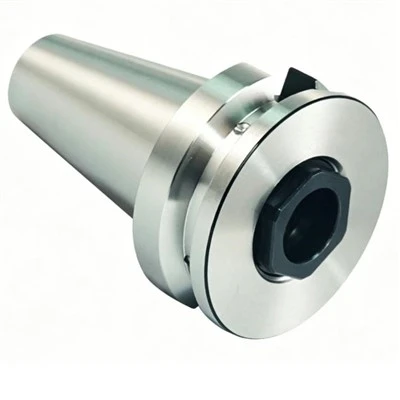

High-Feed Milling Cutters for Automotive Cylinder Heads support high-feed rough milling of suitable cylinder head surfaces, steps and recessed areas. A small approach angle and shallow axial engagement allow high feed per tooth during stock removal. The correct configuration depends on workpiece material, machining allowance, cutter diameter, insert geometry, machine capacity and tool access.
Key Advantages
High Feed per Tooth
A low approach angle supports higher feed per tooth when matched to the cutting geometry and axial depth.
Efficient Roughing
High-feed milling helps remove stock from accessible surfaces and features while maintaining a controlled cutting engagement.
Indexable Tooling
Compatible replaceable inserts allow cutting edges to be renewed without replacing the entire cutter body.
Application-Based Selection
Cutter dimensions, insert geometry and cutting conditions can be matched to the machining task and production requirements.
Automotive Cylinder Head Applications
Surface Roughing
Remove machining allowance from suitable accessible surfaces before subsequent milling operations.
Step Milling
Machine accessible shoulders and stepped features where cutter clearance and engagement permit high-feed cutting.
Recessed Features
Rough mill selected pockets and recesses when tool access, chip evacuation and toolpath conditions are suitable.
Material-Specific Operations
Confirm the cutter and insert grade for the actual aluminum alloy, cast iron or other specified workpiece material.
Technical Specifications
|
Parameter |
Specification (Example: ø50 mm Cutter) |
|
Tool type |
Indexable high-feed milling cutter |
|
Primary operation |
High-feed rough milling |
|
Application |
Automotive cylinder head machining |
|
Cutter diameter (D) |
50 mm (Reference) |
|
Insert count (Z) |
4 teeth |
|
Mounting interface |
Arbor style / Shell mill |
|
Approach angle (κr) |
10° – 15° |
|
Maximum axial depth (ap) |
0.5 mm – 1.5 mm |
|
Radial cutting width (ae) |
Up to 70% – 80% of cutter diameter |
|
Cutting speed (Vc) |
180 – 350 m/min (Alloy dependent) |
|
Feed per tooth (fz) |
0.6 – 1.2 mm/tooth |
|
Coolant method |
Through-tool / External air or coolant blast |
Tool Selection Guide
Workpiece Material
Identify the material grade, hardness and condition. These factors determine the suitable insert grade, cutting geometry and starting parameters.
Stock Allowance
Define the required material removal, axial depth and radial engagement. Match the cutting strategy to the available allowance and tool limits.
Machine Capacity
Check spindle power, torque, toolholding interface, workholding rigidity and cutter overhang against the intended cutting load.
Feature Access
Review the machining drawing for recess depth, adjacent walls, clearances and toolpath entry. Select a cutter diameter that fits the available working space.
Customization Options
Custom cutter configurations can be reviewed against technical drawings and machining requirements. Options for evaluation include cutter diameter, mounting interface, insert arrangement and application-specific dimensions.
Provide the workpiece drawing, material grade, machine interface and intended operation for a technical review. Final dimensions, insert compatibility and manufacturing feasibility should be confirmed before order approval.
Insert Compatibility & Cutting Setup
Insert Matching
Confirm the insert designation, geometry, grade, seating dimensions and clamping arrangement for the selected cutter body.
Cutting Parameters
Set cutting speed, feed per tooth, axial depth and radial engagement using the applicable tool data. Validate the initial setup on the actual workpiece and machine.
Chip Evacuation
Plan chip flow and coolant delivery around the cavity geometry and toolpath. Effective evacuation helps maintain consistent cutting conditions during roughing.
Quality & Manufacturing Control
Dimensional Inspection
Confirm critical cutter dimensions, mounting interfaces and insert seating features against the approved drawing.
Component Verification
Check the cutter body and specified inserts for correct model identification and compatibility.
Technical Documentation
Inspection records, product drawings and applicable material or coating documentation can be identified according to the product configuration and order requirements.
Ordering & Project Requirements
Workpiece Details
Provide the material grade, hardness and cylinder head drawing or machining area.
Machine Information
Specify the mounting interface, spindle capacity and available tool clearance.
Process Requirements
State the machining operation, stock allowance, target production volume and current cutting conditions where available.
Order Configuration
Confirm the required quantity, insert designation and any drawing-based customization. These details help establish the product specification and quotation scope.
Frequently Asked Questions
Q: Which cylinder head materials can be machined?
A: Suitability depends on the exact material grade, insert grade and cutting geometry. Confirm the configuration for the specified aluminum alloy, cast iron or other material.
Q: Can these cutters machine recessed features?
A: They can be considered for accessible recesses when cutter clearance, engagement and chip evacuation are suitable.
Q: How should cutter diameter be selected?
A: Check feature dimensions, tool access, radial engagement, mounting interface and machine capacity against the intended toolpath.
Q: Are custom cutter configurations available?
A: Custom requirements can be reviewed against drawings, machining conditions and manufacturing feasibility.
Q: What information is required for a quotation?
A: Provide the workpiece drawing, material grade, machining operation, required cutter dimensions, machine interface and estimated quantity.
Hot Tags: high-feed milling cutters for automotive cylinder heads, China high-feed milling cutters for automotive cylinder heads manufacturers, suppliers, factory, Drilling and Boring Tools, end mill, End Mills for HRC 60 Hardened Steel, End Mills for Machining Stainless Steel, finishing milling cutter, Solide Carbide Drill