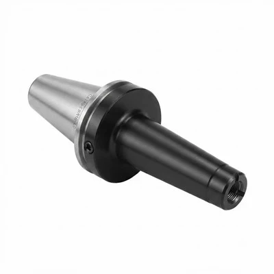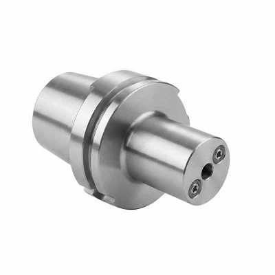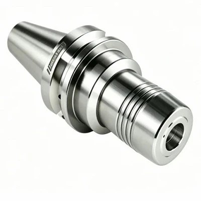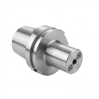
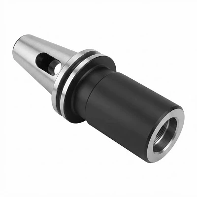
Extended-Length Hydraulic Tool Holders provide additional reach for CNC machining of deep cavities, recessed surfaces and features with limited tool access. An internal hydraulic expansion mechanism clamps compatible cylindrical tool shanks through radial pressure, supporting concentric positioning and repeatable tool setup. The extended body accommodates greater machining depth while maintaining a hydraulic clamping interface. Selection depends on spindle connection, shank diameter, gauge length, nose clearance, spindle speed and coolant requirements.
Key Advantages
Extended Reach
Longer gauge lengths allow cutting tools to reach recessed features and deep workpiece surfaces. The required length should be based on machining depth, tool projection and clearance around the complete assembly.
Hydraulic Clamping
The internal expansion chamber applies radial pressure around the compatible tool shank. Correct shank dimensions and insertion depth support consistent clamping and tool positioning.
Runout Control
Accurate interface and bore geometry help control tool runout. Actual assembled runout depends on the holder, cutting tool, spindle interface and measurement conditions.
Application-Specific Clearance
Nose diameter and body profile determine access around cavity walls, fixtures and adjacent surfaces. These dimensions should be checked against the machining envelope before finalizing the holder.
Technical Specifications
|
Parameter |
Reference Value |
|
Product Type |
Extended-Length Hydraulic Tool Holder |
|
Clamping Mechanism |
Hydraulic Expansion |
|
Spindle Interface |
HSK-A / BT / CAT, subject to model |
|
Clamping Diameter |
6–25 mm |
|
Gauge Length |
100–200 mm |
|
Overall Length |
150–250 mm |
|
Nose Diameter |
20–40 mm |
|
Runout Target |
≤ 0.003 mm, subject to verification |
|
Balancing Target |
G2.5 at 25,000 rpm, subject to verification |
|
Coolant Delivery |
Through-coolant or external, subject to design |
|
Custom Configuration |
Length, interface, bore and body profile |
How to Select the Right Holder
Spindle Compatibility
Identify the spindle interface, size and applicable dimensional standard. The holder taper and seating geometry must match the machine connection.
Shank Diameter
Specify the cutting tool's nominal shank diameter and tolerance. Confirm the required insertion depth and any reduction sleeve requirements before selecting the bore.
Gauge Length
Calculate the distance from the spindle gauge line to the required cutting position. Include tool projection and the clearance needed to reach the target feature.
Machining Conditions
Provide workpiece material, cutting operation, spindle speed and coolant requirements. Long-reach assemblies require suitable tool geometry and cutting parameters to manage deflection and vibration.
Applications
Mold and Die Machining
Reach deep pockets, recessed surfaces and internal cavity walls during precision finishing of complex components.
Precision Drilling
Provide extended access for holemaking operations where tool alignment and consistent positioning are important.
Reaming and Hole Finishing
Support precision finishing of accessible bores when the required reach and tool shank are compatible with the holder specification.
Restricted-Access CNC Machining
Accommodate machining paths where the holder body must clear fixtures, cavity walls or adjacent workpiece features.
Custom Manufacturing
Length and Profile
Specify gauge length, overall length, nose diameter and body profile according to the machining envelope and required tool projection.
Interface and Bore
Provide the spindle interface, clamping diameter and shank tolerance for dimensional review.
Drawing-Based Production
A dimensioned drawing can define critical dimensions, tolerances, coolant passages and interface requirements. Custom production details should be confirmed through drawing review and manufacturing feasibility assessment.
Quality and Inspection
Dimensional Inspection
Check the spindle interface, clamping bore, gauge length and overall length against the approved drawing. Critical dimensions should have defined acceptance tolerances.
Runout Verification
Measure total indicated runout at a specified position using a documented inspection method. Record the acceptance limit and measurement conditions with the inspection result.
Interface Inspection
Verify seating geometry and critical contact surfaces to confirm conformity with the specified spindle connection.
Dynamic Balancing
For high-speed applications, confirm the balancing grade, test speed and applicable configuration. Publish a balancing rating only when supported by the relevant test or production record.
Ordering Information
Holder Configuration
Provide the spindle interface, bore diameter, gauge length, overall length and required nose clearance.
Application Details
Specify machining depth, workpiece material, cutting operation, spindle speed and coolant delivery method.
Acceptance Requirements
State the required runout tolerance, balancing specification and dimensional inspection documentation.
Drawing Review
Attach a dimensioned drawing for non-standard designs. Confirm critical dimensions and technical requirements before approving the final configuration.
Frequently Asked Questions
Q: What is an extended-length hydraulic tool holder used for?
A: It provides additional tool reach for deep cavities, recessed features, precision drilling and bore-finishing operations.
Q: Which clamping diameters are available?
A: Available diameters depend on the confirmed product range. Provide the tool shank diameter and tolerance to identify a compatible configuration.
Q: Can the gauge length be customized?
A: Custom lengths can be assessed against the required machining reach, spindle interface, body dimensions and manufacturing capabilities.
Q: How should runout accuracy be specified?
A: Define a numerical tolerance, measurement position and inspection method. Confirm the acceptance requirement against the machining application and actual product capability.
Q: Is through-coolant available?
A: Coolant delivery depends on the selected design. Specify the coolant route, operating pressure and spindle interface for technical confirmation.
Hot Tags: extended-length hydraulic tool holders, China extended-length hydraulic tool holders manufacturers, suppliers, factory, Boring Bar Tool Holder, CNC Screw in Milling Cutter Holder, end mill holder, HSK Heat Shrink Tool Holder with Water Outlet, threading tool holder, tool holder